

Field dynamic balance correction method
Published:
2019-05-27 10:44
Field dynamic balance is a balance method for vibration measurement, analysis and correction of rotating machinery under field work or close to field work.The field dynamic balance adjustment is only a single measurement correction for the turning machine, which can not solve the problem of force distance unbalance correction on both sides.The following is a brief description of several methods of field dynamic balance.
(I) finding dynamic balance by two-point method:
Including horizontal two point method, vertical two point method.The expression is as follows:
A. horizontal two-point method
Measured fan in the working speed of two bearings vibration amplitude, if A vibration value (Ao), the lateral vibration is to balance A first side and A point on the rotor tick (1) and try to add quality M, the measured vibration value of A1, according to the same radius of the test and quality M mobile 180 ° tick (2), the measured vibration value is A2, according to the measured values of A0, A1, A2, choose appropriate proportion of mapping, and should add the size and location of the balance quality.As shown in figure 1:

FIG. 1 schematic diagram of dynamic equilibrium level two-point method
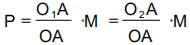
Make OM: OD: DM= A0: a1/2: a2/2, extend MD to C, make CD=DM, and connect OC;Take O as the center of the circle and OC as the radius of the circle O;If the intersection of CO and O circle is extended to B, and the intersection of MO circle is extended to S, then OC is the vibration value caused by the trial addition of mass M (the vibration value after scaling up), and the equilibrium mass P is:

As for the position of permanent counterweight, Angle Angle COS is d as measured in the figure, then the balance mass should be added at the first trial where the mass position 1 reversely turns to Angle or along to Angle d. the specific position is determined by the test. This method requires 5 motor transfers to complete the work of finding dynamic balance.Motor test run times more.
B. vertical two-point method
Measured fan in the working speed of two bearings vibration amplitude, if A vibration value (Ao), the lateral vibration is to balance A first side and A point on the rotor tick (1) and try to add quality M, the measured vibration value of A1, according to the same radius of the test and quality M mobile 90 ° tick (2), the measured vibration value is A2, according to the measured values of A0, A1, A2, choose appropriate proportion of mapping, and should add the size and location of the balance quality.As shown in figure 2:

Figure 2. Diagram of vertical two-point method of dynamic balance
When drawing, radius is A0 value, first drawing, the circle is O, select horizontal radius of a circle O1 (0 °), vertical radius of O2 (90 °).Draw a circle with A1 as the radius, O1 as the center, A2 as the radius, and O2 as the center.Circle O1 and O2 in O circle is center, A0 is in the circle of radius A, there was only one node analysis O ₁ OA and O ₂ OA, according to the general knowledge of mechanics, can know vector should be at 0 ° and 90 ° north of rotor add try M vibration caused by the change.Figure out the size of OA and its Angle with O O and O O, then the weight P can be expressed as:
The location of the permanent weight, according to the O1 (0 °), it turned a corner to reverse;In terms of O2 (90 °), should be turned a + 90 °.The advantage of this method is to determine the counterweight position at one time. It needs a total of 4 times of operation of the motor to effectively reduce rotor vibration.
(2) find dynamic balance by three-point method
This method and two point method basic same, just use the same test and quality M according to certain radius on each other in turn 120 ° on the three directions of measured three vibration value of A1, A2, A3.
The drawing steps are as follows (see fig.3 for the specific drawing) :
1. Take O as the center of the circle, take the appropriate ratio column, and draw a circle with A1, A2 and A3 as the radius;
2. In the small circle, take OA as the side length and OA as the vertex, and make equilateral triangle OAB;
3. Draw a circle with B as the center and the radius of the middle circle as the radius, and the resulting circle intersects the great circle at point C
4. Make equilateral triangle ACD with AC as the side and A and C as the vertices;
5. Make the center point of ACD, denoted as S.Take S AS the center of the circle, AS AS the radius of the circle, OS and S circle intersect at S 'point.
S 'is the position to be added for the balance weight. A, C and D correspond to the three positions to be added for the mass.In this method, the number of motor test runs is 4.
The equilibrium mass P is:

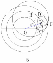
FIG. 3 schematic diagram of dynamic equilibrium three-point method
(3) dynamic balance shall be found by means of flash phase measurement
Its principle is quality of unbalanced rotor vibration caused by disturbing force is produced by centrifugal force, the biggest by the instrument to measure interference force amplitude and phase change, is calculated by using vector unbalanced quality size and location, in the opposite position with equal quality, can be offset due to the uneven quality of vibration.Flash flash time is directly under the control of the vibration phase, when the frequency synchronization speed and flash flash, flash flash every time time is wheel at the same location, flash phase measurement method steps are divided into nine steps, several times to try and balance blocks and start connecting, measured the amplitude and phase, then vector drawing operation, in order to out should add to the quality of the balance weight and position.
It can be seen from this that the reasons why these methods are difficult to be mastered and applied by maintenance personnel are as follows: 1) many steps, long time consuming, repeated trial and weight block;2) complex, need to draw calculation, and the use of special instruments.
(4) find the dynamic balance with the marking method
As we know, the centrifugal force will be generated when the unbalanced rotor rotates, and this force will periodically impact the bearing to generate vibration. We first measured the vibration value of the bearing part with the vibration meter, and mastered the unbalanced state of the rotor under the working state, and then carried out the operation as follows:
1. Select a section near the impeller on the fan shaft that stops rotating, clean its surface, and check to make sure its roundness meets the standard.
2. Start the fan to the working speed, and use the sharpened stone pen to slowly extend into the center line of this shaft segment. When the stone pen just touches the shaft surface, it will stop extending forward, and change to a short distance along the axis and then withdraw, leaving the line segment drawn by the stone pen on the shaft segment.The action must be light and steady, pay attention to the stone pen must not be stretched too far in front, otherwise the shaft will draw the whole circle of arc, the forward extension is not enough, the pen and shaft contact is not enough, draw the line segment or the line segment is not clear, so it is difficult to judge, in the line at the same time, the vibration table can be used to measure the bearing vibration value Ao.
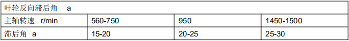
3. After the fan stops, locate the center line a-a of the drawn line segment on the shaft, mark its position with F in other parts of the shaft, and turn a-a line to the horizontal position. After the symmetrical position of the horizontal line is reversed in the rotation direction of the impeller, A phase Angle is added as emphasis.Its hysteresis Angle is shown in the following table:
4. The counterweight shall be selected according to the empirical data and welded on the front or rear edge of the fan to the non-working face.Start the fan again and measure its amplitude with the vibration meter. If it meets the requirements, the work will be finished. If the amplitude does not meet the requirements, the dynamic balance needs to be found again.
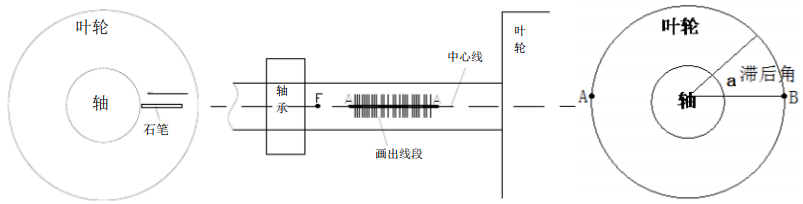
FIG. 4 schematic diagram of dynamic balance scribing method
Compared with other methods, the one-line method is simple to operate, short working time, and requires 2-3 times of transfer trial, which has great application advantages.However, the selection of balance and lag Angle must have some experience, which must be the accumulation of correction and balance work.
Related news
2018-12-03
In addition, if you need to buy a balance test machine, please contact us directly.
2018-12-03
Safety operation of the rotor of the motor to be balanced
电机转子装配工的一般操作规程如下: 1、工作前,整理场地,放稳各零、部件,并检查装配使用工具和工作环境是否安全良好。 2、吊放电机机座、底板、定子、转子、轴承等大型部件时必须放好方箱或垫木...
2018-12-03
Rubber roller dynamic balancing machine customer site
Mainly used in the balance correction of high-speed rotating workpieces in various household appliances
2018-12-03
Mainly used in micro-motor rotors, such as automotive motors, household electrical appliances, micro-motors
2018-12-03
[Guangzhou Zhuo Xuanjin] balance machine application range
Dynamic balancing machines are widely used and can be divided into ten categories
2018-12-03
Guangzhou Zhuo Xuanjin various balance machines and their application range
Mainly used in the balance correction of high-speed rotating workpieces in various household appliances, cooling fans, motors, generators, pumps, automobiles, printing, rollers and other industries.