

Sources and methods of expression of unbalance in the rotor
Published:
2019-05-27 11:53
A rotor is usually designed so that it is axially symmetric relative to the axis of rotation.However, due to a series of factors in the processing process, the final assembly of the rotor is always not able to complete the axial symmetry of the driving force, there is some imbalance.
Such imbalances are commonly referred to as initial unbalances.The key factors that cause initial unbalance are:
1. Unevenness of rotor materials:
2. Imbalance of coupling:
3. Imbalance caused by asymmetric keyway.
4, rotor processing will always cause some roundness error and eccentricity;
5. Harm of impeller's unbalance;
The unbalance caused by these factors is random and cannot be calculated. Therefore, it should be measured and corrected according to gravity test (static balance) and rotation test (dynamic balance) to reduce it to the permissible level.
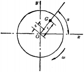
FIG. 1 unbalance of a wafer
If the thickness of a rotor is divided into glass for Δ z, then each wafer (shown in figure 1) there is a unbalance.It is identified that the unbalanced mass with size G exists in a place with radius r and circumference reference Angle, then the centrifugal force generated by it is:

In the equation, omega is the angular velocity.Therefore, the centrifugal force F increases with the increase of.Therefore, the product of G and r becomes unbalance, which is generally expressed as:
|U| Gr = (or U = Gr)
The unit is usually g mm, then:

So the centrifugal force is directly proportional to the unbalance.

The unbalance is a vector which belongs to the direction and is generally expressed as:
Since the size and direction of each wafer are different (as shown in FIG. 2 and FIG. 3), the rotor's unbalance is a function of the axis coordinates.Because the paper focuses on the dynamic balance of the impeller adjustment, do not do a detailed description.

FIG. 2 unbalance of a rotor

FIG. 3 distribution function of unbalance
Related news
2018-12-03
In addition, if you need to buy a balance test machine, please contact us directly.
2018-12-03
Safety operation of the rotor of the motor to be balanced
电机转子装配工的一般操作规程如下: 1、工作前,整理场地,放稳各零、部件,并检查装配使用工具和工作环境是否安全良好。 2、吊放电机机座、底板、定子、转子、轴承等大型部件时必须放好方箱或垫木...
2018-12-03
Rubber roller dynamic balancing machine customer site
Mainly used in the balance correction of high-speed rotating workpieces in various household appliances
2018-12-03
Mainly used in micro-motor rotors, such as automotive motors, household electrical appliances, micro-motors
2018-12-03
[Guangzhou Zhuo Xuanjin] balance machine application range
Dynamic balancing machines are widely used and can be divided into ten categories
2018-12-03
Guangzhou Zhuo Xuanjin various balance machines and their application range
Mainly used in the balance correction of high-speed rotating workpieces in various household appliances, cooling fans, motors, generators, pumps, automobiles, printing, rollers and other industries.