

Rotor mass imbalance
Published:
2019-05-29 15:07
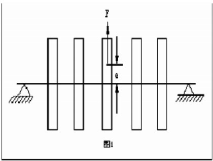
FIG. 1 shows the vibration of a multi-disk rotor with eccentric mass.If the influence of gyro force is ignored, the steady-state response caused by unbalanced vibration force can be calculated by using the single-degree-of-freedom forced vibration response formula after the coupling of the rotating subsystem is uncoupled by using the modal coordinates.It can be seen from the analysis that the vibration characteristics of the rotor imbalance are:
(1) the central track of the disk is a circle or ellipse.
(2) the steady-state vibration of each disk is a forced vibration of the same frequency as the rotation speed, and its amplitude changes with the rotation speed according to the resonance curve law in the vibration theory, reaching the maximum value at the critical rotation speed.Therefore, the prominent characteristic of rotor unbalance fault is large amplitude of one-octave vibration.
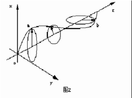
(3) represents the complex vector phase Angle of displacement at the center of each disc is different, so the axis bends into a spatial curve and rotates around the oz axis with rotor speed, as shown in figure 2.
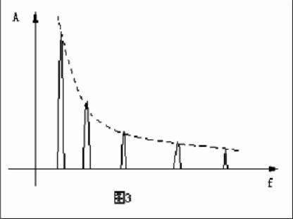
(4) the vibration size of the bearing in different directions is not the same due to the different stiffness of the bearing in different directions, the nonlinear of the oil film damping and the nonlinear of the rotor and other factors.The stiffness in the horizontal direction is small, and the vibration amplitude is large, so that the whole spectrum shows the shape shown in FIG. 3.
The unbalanced rotor causes vibration during rotation, which can be detected by sensors.The sensor can be mounted on the frame to measure the vibration of the rotating shaft relative to the frame, or it can measure the absolute vibration of the frame.Usually, a mark is made on the rotor, which is detected by the photoelectric sensor as a reference for calculating the unbalanced Angle position.Due to the influence of bearing noise and ambient vibration, the signal of vibration sensor contains a lot of noise.However, it can be confirmed from the above analysis that only the part with the same frequency as the rotor is caused by the rotor imbalance.By using the signal of photoelectric sensor and vibration sensor, the square wave or sine wave signal with the same frequency of rotation speed can be obtained through waveform transformation.
Related news
2018-12-03
In addition, if you need to buy a balance test machine, please contact us directly.
2018-12-03
Safety operation of the rotor of the motor to be balanced
电机转子装配工的一般操作规程如下: 1、工作前,整理场地,放稳各零、部件,并检查装配使用工具和工作环境是否安全良好。 2、吊放电机机座、底板、定子、转子、轴承等大型部件时必须放好方箱或垫木...
2018-12-03
Rubber roller dynamic balancing machine customer site
Mainly used in the balance correction of high-speed rotating workpieces in various household appliances
2018-12-03
Mainly used in micro-motor rotors, such as automotive motors, household electrical appliances, micro-motors
2018-12-03
[Guangzhou Zhuo Xuanjin] balance machine application range
Dynamic balancing machines are widely used and can be divided into ten categories
2018-12-03
Guangzhou Zhuo Xuanjin various balance machines and their application range
Mainly used in the balance correction of high-speed rotating workpieces in various household appliances, cooling fans, motors, generators, pumps, automobiles, printing, rollers and other industries.