

PRODUCTS

CONTACT
Guangzhou Zhuoxuanjin Machinert Equipment co.Ltd
Fax:020-36969822
Add:No. 34, Dahua Street, Huadu District, Guangzhou, Guangdong
XCPH-11 Field balancing machine

XCPH-11 Field balancing machine
Small size, light weight, easy to carry. New test concept and powerful software features, friendly display interface and menu-based operation.
key word:
On-site dynamic balancer
portable dynamic balancing machine
miniature balancing machine
- Description
- Image display
- Product parameters
- Customer site
- Troubleshooting
-
XCPH-11 Field Balancer· Product advantages1. Small size, light weight, easy to carry. New test concept and powerful software features, friendly display interface and menu-based operation.2. The display part adopts touch-type liquid crystal display, the display is clear, and the new system can automatically retain the previous measurement result while measuring, and it is convenient to analyze the problems occurring in the calibration. Reduce the number of judgment errors and corrections.3. A balancer that uses the influence coefficient method to measure. The accuracy of the measured value has an important relationship with the operating speed of the measurement, the magnitude of the calibration, and the position of the sensor.Dimensions: length × width × height 320 × 230 × 180
 Side panel
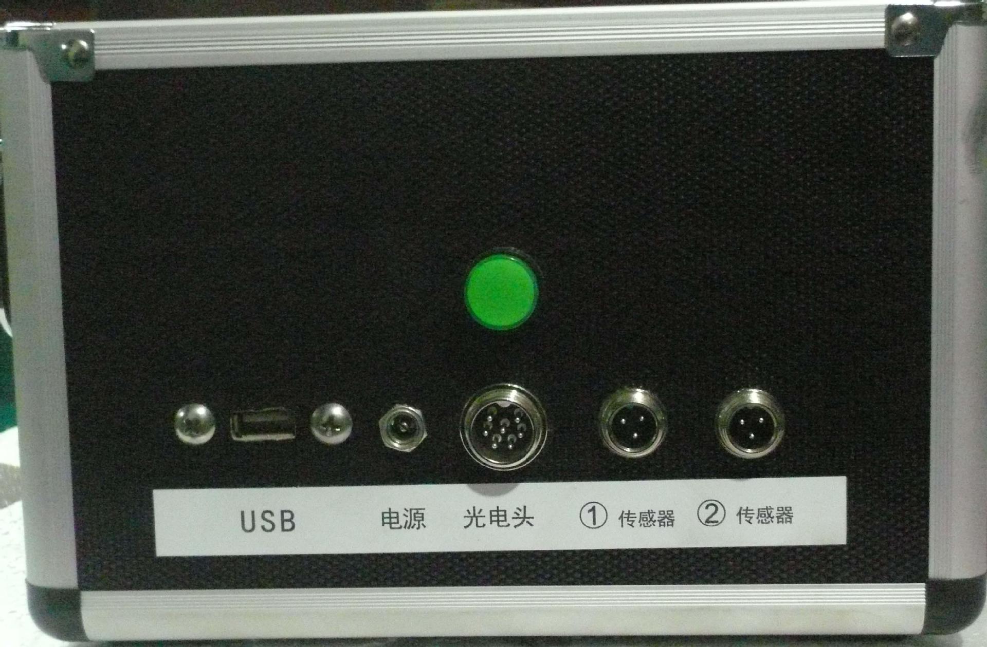 I. OverviewThe SDM-811 single- and double-sided on-site dynamic balancer carefully developed and produced by the company provides you with a solution that cannot be solved by ordinary balancing machines--the assembly dynamic balance.After the product is assembled, the rotating body will produce a phenomenon that does not meet the designer's desired effect due to process or other reasons. This is the vibration phenomenon caused by the workmanship, the deformation of the assembly, and the like. The vibration and displacement caused by the imbalance of the rotating body during operation can be greatly destructive. Greatly reduce the safety and longevity of equipment operation. For example, the impeller of the fan industry, the huge centrifugal force and mechanical vibration caused by the imbalance will cause the installation screws to break, the bearing wear and fatigue fission. Eventually it causes cracking or deformation of the rotation. These will shorten the life of the fan and pose a danger to the operator. With the on-site balancer, you can measure and correct the impeller without removing the fan impeller until the vibration is removed and the standard is reached.Dynamic balancerModern life has brought us a lot of new products from abroad. When we develop such products, we will bring a lot of new ideas in the processing industry. Such as: copy machine tools, CNC machine tools, etc. Its emergence has brought a new leap in the industry. However, when using such a machine tool to process some special workpieces, the machining position is not at the center of the fixture due to the special shape, and the workpiece is in an eccentric position. At this time, a certain weight should be attached to the eccentric clamp to minimize the vibration caused by the deviation of the rotation center. The machining speed of the workpiece is greatly improved, and the tolerance caused by the vibration is reduced, that is, the efficiency and the yield of the workpiece are improved.SDM-811 single and double-sided field balancer is your best assistant. Its compact size and light weight make it easy to carry. Its new test concept and powerful software features, friendly display interface and menu-based operation make it easy for even inexperienced operators to quickly measure and eliminate rotor imbalances in minutes.
 The display part of the SDM-811 single and double-sided field balancer adopts a touch-type liquid crystal display, and the display is clear. The new system can automatically retain the last measurement result while measuring, so that you can easily analyze it in the calibration. The problem that arises. You can reduce your judgment errors and the number of corrections. It is the ideal instrument for the machinery industry and the fan industry.
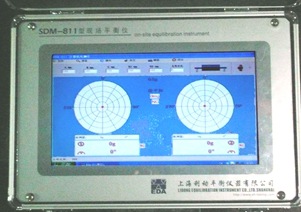
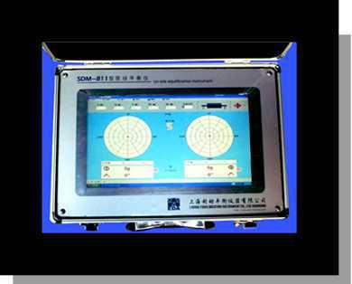
 The SDM-811 single and double-sided field balancer uses the influence coefficient method to measure the balance meter. Its measured value accuracy is the working speed when it is measured, the scaled value, and the position of the sensor. There is an important relationship. When the measured speed range is low, the weight of the calibration should be larger due to the lower line speed; on the contrary, the weight of the workpiece measured at the high speed can be smaller, and the calibration value is not easy to fly out during the measurement. should.
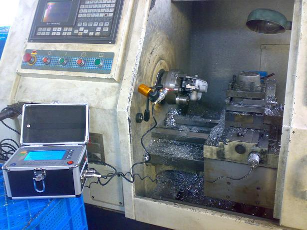 Second, the computer briefly worksWorking principleWhen the rotor rotates, the signals generated by the sensors mounted on the two test faces are applied to two identical input switch circuits. The component values of the switching circuit are different on different balancing machines.The signal is integrated to eliminate the influence of the rotational speed, and then filtered to filter out the clutter signal, which is added to the automatic program-controlled amplifier circuit. After amplification, it is converted into a digital signal by AD conversion, and the digital signal is processed by the computer, and finally It is displayed on the screen.Third, the balance meter installation and connectioninstallation method1) Hold one or two sensors with a magnetic seat on the bearing housing in the radial direction. Connect the sensor to the host computer with a cable.2) Connect the photo sensor line to the socket on the main unit3) The power supply of the unit uses 220v AC voltage and plugs the power cord into the socket.four. Computer interface description1) menu items, computer various function options:Includes opening, saving, deleting, interface switching, workpiece calibration, printing, setting, and exit of the rotor number.2) Working parameter input area: including A B C R1 R2 and support mode. (This site balancer support mode only selects 8 and 9, other do not choose)3) Interface: There are 3 kinds of interfaces for switching (vector, waveform, record table).4) Display the left unbalance amount and the left angle.5) The current actual speed (unit: r/min) can be directly displayed.6) Weighting mode or deduplication mode adjustment: Click (de-heavier or weighted symbol) to switch the weighting, and the weight correction method7) Display the right unbalance amount and the right angle.8) Communication window, the word “S” printed on the upper right corner of the screen is the identification of the working of the balance machine. The red character is normal for serial communication, and the blue word is abnormal for serial communication.9) The number of grams displayed in the center between the two dials indicates the current dial full scale.10) The dial red dot is also used to indicate the correction angle and amplitude.11) The angle and unbalance of the previous measurement.12) The currently measured static balance value.13) indicates the qualified range. NG means unqualified, OK means qualified (determined by the customer)Fives. operating1. Support mode selection: Select range 8 or 9, which can be input directly.It is not necessary to input a, b, c, r1, r2 for the soft support state of the support modes 8 and 9.2. Print: One Select the current data print or full screen copy print in the file option in the upper left corner of the screen.2. Press the right mouse button on the history table to select history printing.3. Exit: Turn off the measurement system. At this time, you will be prompted to save the data file.4. set up:1) Qualified range setting: If the left and right qualified range is set to 0, then the qualified range setting does not work. If the value is not 0, the actual measured data is less than the set value during the measurement, that is, OK is displayed. qualified).2) Calibration factor setting: Under normal conditions, the calibration factor will be automatically generated after the calibration is completed.3) Measurement times setting: 4 to 32 selection range. If set to 8, the system automatically locks the magnitude and angle after 8 measurements, and the magnitude and angle color turn red. The measurement ends. If set to 32, the system will continue to measure. Values greater than 32 or less than 4 are invalid.(Note: After the measurement times are set, enter the password 33 in the password box below, and then press OK).4) Enter 123434 in the password box: Switch between widescreen and narrowscreen.Enter mg in the password box: The measurement result shows mgEnter g in the password box: measurement result shows g5) Index setting: Enter the division value to divide the circle into equal parts, the range is 3-32 and enter 33 in the password box to confirm. (Note: Each time you turn the phone on or re-enter the system, you must confirm it by entering "33" in the password box.5. Select the “Keyboard” menu to bring up the on-screen keyboard.Seven. System calibration:The support mode is set to 8 or 9 (8 is double-sided 9 for single-sided). Different machine measurements must be recalibrated due to changes in the mounting position of the sensor and the photocell. The same machine can be measured with the original calibration data if the sensor and photocell have not moved. The calibration process is as follows:Select “Operation” “Scale” in the menu and then press the prompt to start the calibration operation.1. When the support mode is “8”, it is measured on both sides. (You can press the Keyboard menu to bring up the on-screen keyboard to change the support mode. You can use the on-screen keyboard for all keyboard input later.)The first step (1) adds a known test weight to an angle to the left of the workpiece (generally added to zero). Figure:(2) Enter the magnitude and angle of the test weight.For example: Left test weight (g) Left angle (°)1.1 0(3) Start-up measurement (Note: If the machine is slowing down and slowing down each time, you need to unplug the photoelectric head plug for each speed of the lift, and then connect it after the speed is stable. Otherwise it will affect the calibration result)(4) Shut down when the red “ok” appears, and the left calibration ends.The second step (1) moves the left test weight to an angle to the right of the workpiece (generally added to zero).For example: Right test weight (g) Right test weight (g)11 0(2) Enter the magnitude and angle of the test weight.(3) Start measurement.(4) Shut down when the red "ok" appears, and the calibration on the right ends.The third step. Take the test weight off and start the measurement. A red "end" calibration is completed and the input save file is promoted.After saving, the measurement is entered.2. When the support mode is "9", it is single-sided. At this time, attention should be paid to the calibration. When the test weight is added to 0 degree, the input angle should be 0 degree. The operation is as follows:The first step(1) adds a known test weight to an angle to the left of the workpiece (generally added to zero).(2) Enter the magnitude and angle of the test weight. Figure:For example: Left test weight (g) Left angle (°)1.1 0(3) Start measurement(4) Shut down when the red “ok” appears, and the left calibration ends.The third step. Take the test weight off and start the measurement. Red "end" calibration is completed and the input save is savedAfter saving, the measurement is entered.Eight. Precautions:1. The setting of the sensor should be placed in the radial position, generally set on the side of the bearing seat, the guide rail of the machine tool, and the bearing seat of the front box. It should not be set at the top, and it should be placed in a place where the sensor magnet can be stably and firmly absorbed.2, the photoelectric head is based on reflective paper reflection as a reference, should not be against the background of bright light. Place it in places such as the sky and lathe lights where there is a light source. The angle at which the reflective paper is adhered is generally set to 0 degrees, and the angle is calculated by calculating the angle in the reverse direction of the rotation direction. Figure:nine. Repair and maintenance1. This machine is a precision instrument and should be used by a person. Non-operators should not tamper with it to avoid malfunction and affect production.2. When using, keep it well ventilated, avoid direct sunlight or close to other heat sources to keep the instrument working at room temperature.3. The machine should be dust-proof and moisture-proof, and the user should take corresponding measures.4. If the screen is too dusty, wipe it gently with a soft cloth.5. Disconnect the main power supply when not in use. When not in use for a long time, you should elect at least half an hour per month.6. There are no user-adjustable components in the machine. Please do not adjust the components on the board.7. When an abnormal phenomenon occurs, turn off the power and unplug the power plug.ten. General faults and countermeasuresXI. Features of the machine's technical parameters1, the speed range: 180 ~ 5000 rev / min2. The minimum unbalance can be measured to 0.01g, the error is ≤10%3. Working environment temperature: 0~60°C4. Working environment humidity: 5%~95%5. Power: 187~253V 45~60HZ
 -
-
-
Related products
Get product quotes for free